Why Is Your Peristaltic Pump Running Hot? (Mechanical & Electrical Diagnostics)
The overheating of the peristaltic pump is usually not due to abnormal heating of the motor or the driver, but rather is caused by mechanical loads, hose friction, or poor heat dissipation, resulting in excessive temperature rise of the pump head or the driver. A slight increase in temperature (usually not exceeding 40°C or 50°C) is a normal thermodynamic by-product of mechanical compression and motor operation, but a pump body temperature exceeding 60°C or a feeling of heat is a serious warning signal. Overheating not only causes inconvenience but also leads to flow drift, significantly shortens the lifespan of the pipeline, and may damage the internal components of the motor.
Two Main Sources of Peristaltic Pump Overheating
The mechanical friction at the pump head and the electrical energy loss within the motor are the main causes of the overheating of the peristaltic pump:
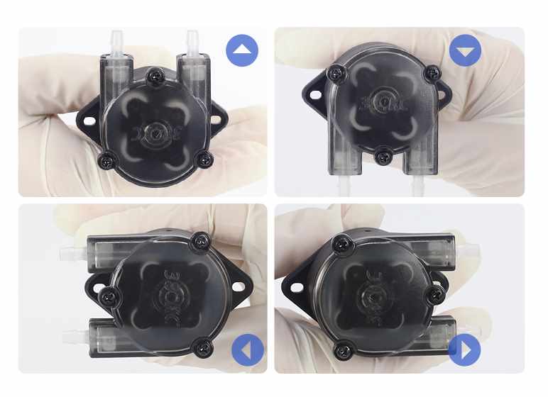
Mechanical Pathway: Pump Head Friction and Material Strain
The working principle of the peristaltic pump – that is, by continuously applying mechanical compression to the elastic tube – is the main source of thermal energy.
- Excessive compression: If the gap between the roller and the track is set too small, or if the wall thickness of the pipe does not perfectly match the specifications of the pump head, the roller will excessively compress the elastic body. This excessive compression will directly convert mechanical energy into frictional heat.
- Bearings deterioration: A less obvious but very serious mechanical problem is that the miniature bearings inside the rollers start to fail. If chemical liquids splash onto the rollers or the factory lubricant dries up, the rollers will not be able to rotate freely. Sliding friction replaces rolling friction, causing the temperature inside the pump head housing to rise rapidly and sharply.
- Lagging loss: When the roller rapidly presses and releases the pipe material, the elastic polymer chains will repeatedly deform and recover. This cyclic stress will cause molecular friction within the pipe, known as lagging loss. This phenomenon becomes significantly more pronounced at higher rotational speeds (RPM).

Electrical Causes: Motor Overload and Driver Heat Buildup
Usually, the sensation of the pump getting hot is actually the heat that is transmitted through the drive shaft from the overloaded motor.
- The low-speed paradox of stepper motors: Many compact peristaltic pump systems use stepper motors. Due to the physical characteristics of constant current chopping drive, stepper motors consume the maximum current at extremely low speeds or when maintaining a position. Therefore, operating the pump at a low speed (for example, <20 RPM) under high load will cause the temperature of the motor winding to be significantly higher than that at medium speeds.
- System backpressure and fluid viscosity: When pumping high-viscosity fluids (such as heavy oil or chemical polymers) or transporting fluids through long and narrow discharge pipes with multiple bends, the system backpressure will increase. The motor must output close to its maximum torque to overcome this resistance, thereby consuming higher continuous current and generating a large amount of heat loss.
Step-by-Step Troubleshooting Process
If a peristaltic pump in your facility is running critically hot, follow this systematic diagnostic process to isolate and resolve the issue.
Step 1: Thermal Isolation Test
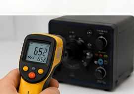
Safely power down the system and remove the pump head from the motor drive shaft. Use an infrared thermometer to measure the temperature of the motor housing and the pump head casing separately.
Diagnosis: If the motor is extremely hot but the pump head is cool, the issue lies in the electrical/drive settings. If the pump head is significantly hotter than the motor, the root cause is mechanical friction.
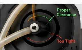
Step 2: Check Tubing Size and Roller Clearance
Inspect the running tube. Measure its wall thickness with a digital caliper and check for “swelling”—a common sign of chemical incompatibility where the fluid alters the polymer matrix, increasing its physical size.
Adjustment: If your pump features an adjustable-occlusion design, gradually loosen the pressure setting while the pump is running. Find the exact point where backflow (slip) stops; do not tighten it any further. Over-tightening provides zero performance benefit and only generates destructive heat.
Step 3: Inspect Lubrication and Roller Movement
Inspect the roller assembly. If the roller surfaces appear dry, polished, or show signs of fine metallic debris, the mechanical interface is starved of lubrication.
Adjustment: Clean away any old debris and apply a thin, uniform layer of a high-temperature, synthetic, silicone-based grease to the outer surface of the tubing and the rollers. Never use petroleum-based lubricants, as they will aggressively degrade silicone, TPE, and fluoroelastomer pump tubing.
Step 4: Reduce Back Pressure and Flow Resistance
Check the fluid dynamics of your plumbing layout. If the inlet line is restrictive or the fluid viscosity is high, the pump has to fight severe fluid resistance.
Adjustment: Instead of running a small-bore tube at a high RPM to achieve your target flow rate, upsize to a larger inner diameter (ID) tubing and lower the pump’s rotational speed (RPM). This maintains your target flow rate while drastically reducing both fluid velocity resistance and the tubing’s hysteresis heat generation.
Step 5: Adjust Motor Driver Current Settings
Open the electrical control cabinet and inspect the stepper/servo driver configuration.
Adjustment: If the motor has excess torque capacity for the application, lower the output current setting via the driver’s DIP switches by 10% to 20%. Additionally, ensure that the “automatic idle current reduction” (or half-current mode) is enabled. This feature cuts the current in half when the pump is paused, preventing severe static overheating.
Peristaltic Pump Overheating Prevention Checklist
To prevent thermal issues before they cause unplanned downtime, implement the following checklist into your facility’s routine maintenance schedule:
| Maintenance Interval | Target Checkpoint | Expected Technical Status |
| Per Shift | Visual inspection of tubing and touch-test. | Casing temperature $<50^\circ\text{C}$; no visible blistering or cracking on the tube exterior. |
| Weekly | Roller rotation check. | Disengage the tube; rollers must spin freely on their shafts with zero binding or axial play. |
| Every 200 Hours | Lubricant replenishment. | Wipe clean the old tracking path and apply a fresh film of specialized synthetic silicone grease. |
| Quarterly | Electrical and ventilation audit. | Verify motor current draw matches nominal design; clean dust build-up from motor cooling fins and enclosure fans. |
If the pump body (excluding the motor) feels hot to the touch (above 60℃), first check for mechanical friction between the hose and the pump head; if the entire drive unit is overheating, focus on the issues of motor load, power supply, or cooling. Immediately stop the machine to cool it down, then check each item in the sequence of “hose condition → installation specifications → speed load → drive ventilation” to avoid damaging the motor or rollers due to continued operation in a faulty state.