
How to Connect and Control a DC Peristaltic Pump Motor?
In contemporary technology, especially in different industrial sectors, fluid transferring systems require particular attention related to the DC peristaltic pump, which remains an essential and versatile tool. Each DC peristaltic pump contains a power source, usually a DC motor, which drives the unique and precise fluid transfer control within the pump.
Specialist engineers, hobbyists and technician workers in the process of controlling fluids in systems, connecting to and controlling the motors of the DC peristaltic pump may seem like a daunting task at the beginning. We detail the control and connection of the pump in the article, and discuss some of the most frequent errors and methods for avoiding them.

What Is a DC Peristaltic Pump Motor?
The DC peristaltic pump uses a DC motor to rotate the rollers inside the pump head, thereby compressing and releasing the flexible hose. This action generates a peristaltic movement, causing the fluid to move. The liquid does not come into contact with the motor or internal components – it only touches the hose.
Peristaltic pumps mainly use two types of DC motors:
Brushed DC Motor:
- Commonly seen in entry-level pumps
- Simple control (voltage = rotational speed)
- Low cost
- Due to the wear of the brushes, their service life is relatively short
Brushless DC Motor (BLDC):
- Higher efficiency and longer lifespan
- A dedicated driver/controller is required
- Quieter and more durable
Why use DC motors instead of stepper motors?
Smaller in size, cheaper in price, and easy to power with a simple circuit, DC motors are ideal for low-cost or space-constrained applications where speed control matters more than precise positioning.
How to Connect and Control a Peristaltic Pump Motor?
Connecting and controlling a peristaltic pump motor includes supplying the correct amount of power, using a motor driver, and interfacing with a control source safely. Here is a more efficient guide.
Step 1: Supply the Correct Power
In this step please make sure that the power supply aligns with the specifications of the motor. The voltage, such as 12V or 24V, must be accurate, and the current rating of the power supply must exceed the motor’s rated current so it can run properly and safely without getting damaged.
Step 2: Determine the Control Approach
Remember that you have two main options for control:
A) Basic On/Off Control
For an easier approach, you can connect the motor to the power source using a switch. This method will provide on/off functionality with full speed. Reversing the motor’s direction can be done by switching the connections to the motor terminals.
B) Controlled Variable Speed
For accurate control of the flow and its direction, a motor driver (e.g., L298N, DRV8871) is connected between the motor and a microcontroller (Arduino, Raspberry Pi). Never connect a microcontroller with its pins to a motor as this will cause irreversible damage to the controller.
The connection is straightforward:
- Connect Power: Wire the main power supply to the motor driver’s power input.
- Connect Motor: Connect the two terminals of the motor to the motor output of the driver.
- Connect Controller: Connect the control pins of the driver to the digital output pins of the microcontroller.
Step 3: Implement Control Logic
Now that the components are integrated, the motor may be controlled via software running on the microcontroller.
- Speed Control: Activate the motor driver ‘Enable’ (ENA or PWM) pin via PWM with a pulse-width modulated signal from the microcontroller. The average voltage supplied to the motor, and thus its speed, will be controlled via the signal’s duty cycle (0% to 100%).
- Direction Control: Control the two digital pins and send the signal to the driver ‘Input’ pins (e.g., IN1, IN2). If these pins are set to opposite logic states, the motor will change its direction of rotation.
With appropriate programming on the microcontroller, the pump’s speed and direction can be controlled automatically and precisely, which are crucial for dosing and metering tasks.
Common Mistakes and How to Avoid Them
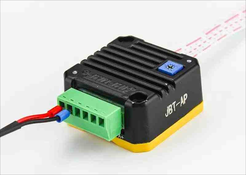
While understanding the connection and control process for DC peristaltic pumps can simplify things, lack of attention to detail can lead to project failure, delay, or damage to components.
- Using the incorrect power supply:
A voltage that is too high can damage the motor, and a low voltage will lead to the motor underperforming.
Resolution: Follow the specifications exactly, make sure to validate voltage and current requirements and that the power supply is in fact greater than the rated voltage. Additionally, the motor needs to be provided sufficient current, especially the “stall current” required during startup. - Connecting the motor directly to a microcontroller:
I/O microcontroller pins only provide low-power signals, and the current supplied is in the order of 20-40mA. Drawing power via those pins will lead to damage.
Avoidance strategy: Whenever a motor needs to be controlled, the only safe method is to put drivers, relays, or MOSFETs in between the microcontroller and motor. With a proper motor driver the low current control signals via the microcontroller can safely and reliably control the motor. - Inefficient heat dissipation of the motor driver:
The motor driver overheats, especially when the motor is operating under high current load, which is common during motor driving. Excessive heat can lead to the driver overheating temporarily, and in more severe cases, overheating can cause permanent damage to the driver.
Avoidance strategy: The majority of motor driver boards have heat sinks. Check that the heat sink is properly mounted to the driver IC. Implement active cooling options, like small fans, if the operating current is near the upper threshold of the maximum current limit of the driver. - Electrical:
Use of inappropriate wiring dimensions can lead to poor interconnections which can cause intermittent operation, significant voltage drops, and even fires.
Avoidance strategy: Use appropriate wire gauges that match the current size of the motor. Check that the connections are secure which can be achieved through proper welding, reliable screw terminals, or with connectors that are known to hold firm. The wire length should be minimal to reduce resistance.
Need Help Selecting the Right Pump or Motor?
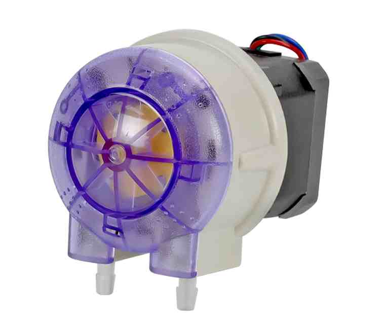
Selecting the appropriate peristaltic pump is essential in both scenarios: constructing a bespoke dosing system and when acquiring pumps for industrial machinery. Do not hesitate to reach out to us if you require specific guidance for a peristaltic pump or motor selection for your project. JIHPUMP is ready to offer you tailored fluid handling systems optimized for your application.