Peristaltic Pump Tubing Sizes: What are They and How to Choose?
In peristaltic pump applications, while the pump head, driver, and control system are undoubtedly important, the tubing is the true core component that directly contacts the medium and dictates the fluid transfer performance.
Many users focus solely on flow rate and pressure parameters during selection, overlooked the critical importance of tubing size. In reality, incorrect tubing dimensions not only compromise flow accuracy but can also drastically shorten tubing lifespan, accelerate pump head wear, and lead to unexpected equipment downtime or costly product waste.
This guide provides a comprehensive analysis of peristaltic pump tubing sizes, comparing standard specifications, examining flow rate correlations, and outlining selection techniques for actual working conditions.
What are Peristaltic Pump Tubing Sizes?
The dimensions of peristaltic pump tubing sizes are determined based on the inner diameter (ID), outer diameter (OD), and wall thickness.
The three properties together govern the flow capacity, strength, and compatibility of the tubing with respect to the pump head.
Inner Diameter (ID) determines flow rate: because it dictates the volume of fluid carried in the tube per occlusion by the rollers.
Wall Thickness determines lifespan and pressure capacity: It dictates the restitution speed (the ability of the tubing to snap back to its original shape after occlusion) and the maximum system backpressure it can withstand.
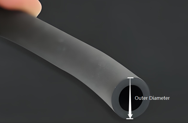
Outer Diameter (OD) determines physical compatibility: It ensures the mechanical fit between the tubing and the pump head’s rotor track.
In industrial and laboratory applications, these parameters adhere to the following formula: OD =ID + 2*Wall Thickness
How Inner Diameter (ID) Impacts Flow Rate
The Inner Diameter (ID) is the diameter of the internal fluid channel and acts as the most direct factor influencing flow rate.
Under identical roller configurations and motor speeds:
Larger IDs yield higher flow volumes per revolution. From a fluid dynamics perspective, the theoretical flow rate is proportional to the square of the inner diameter.
Smaller IDs yield lower flow rates but offer higher metering precision. A smaller ID provides finer resolution at low flow rates and effectively dampens pulsation during roller transitions.
Typical Applications by ID:
- 0.8 mm ID: Commonly used in laboratory micro-metering, chromatography, and microfluidic chips.
- 1.6 mm ID: Ideal for precision chemical dosing, medical dialysis, and reagent micro-titration.
- 3.2 mm ID: Suitable for general industrial fluid transfer and pilot-scale fermenter feeding.
- 6.4 mm and above: Deployed in high-flow operations, bulk filling, chemical dosing, and wastewater treatment.
Selection Tip: Laboratory instruments, medical devices, and analytical equipment generally utilize small-bore tubing to achieve stable, precise flow control. Conversely, chemical, food, and wastewater industries favor large-bore tubing to boost transfer efficiency. For high-viscosity fluids (such as glycerol or inks), a larger ID is mandatory to minimize flow resistance.
Why Outer Diameter (OD) is Equally Crucial?
A frequent misconception is that only the inner diameter matters. However, the Outer Diameter (OD) is equally vital because it determines how securely the tubing fits within the pump head track, establishing the correct compression fit between the rollers and the occlusion wall.
If the OD is too small: The rollers cannot fully compress the tubing, preventing complete occlusion. This causes fluid backflow, flow instability, and severe slippage. It can also cause the tubing to migrate axially within the pump head (commonly known as “tube walking”).
If the OD is too large: The tubing becomes overly compressed within the track. This makes installation exceptionally difficult and spikes mechanical stress. Consequently, the tubing suffers accelerated shear fatigue, causing its operational lifespan to plummet, and the excessive friction can overload, overheat, or burn out the motor.
Always double-check both ID and OD dimensions against the manufacturer’s technical manual to ensure compliance with mechanical tolerances.
The Impact of Wall Thickness on Tubing Lifespan
Wall thickness is the parameter most frequently overlooked by users, yet it directly governs:
Restitution Performance: The speed at which the tubing returns to its original shape after the roller passes, creating the vacuum suction required for lift.
Fatigue Resistance: The mechanical lifespan needed to withstand millions of continuous occlusions.
Pressure Resistance: Prevention of tubing swelling or bursting under outlet backpressure.
Advantages of Thicker Walls:
Higher Pressure Handling: While a 1.6 mm wall thickness typically handles only 0.1 MPa of pressure, a 2.4 mm or 3.2 mm wall thickness can sustain continuous backpressures above 0.2 MPa.
Non-Collapse Property: At high vacuum conditions (high suction lift), the thicker wall structure prevents collapsing.
Suitable for Continuous Use: Thicker wall tubes have excellent mechanical strength and stability.
Note: Thicker wall increases the ability to resist occlusion and adds loading to the drive system, thus necessitating high torque motor.
Common Wall Thickness Standard Categories:
0.8 mm: Ultra-micro, highly flexible pump tubing.
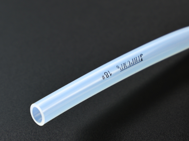
1.6 mm: Thin-wall tubing; the most common standard specification (e.g., Thin-Wall series 13#, 14#, 16#, 17#).
2.4 mm / 3.2 mm: Industrial-grade thick-wall tubing; highly pressure-resistant and durable (e.g., Thick-Wall series 15#, 24#, 35#, 36#, 73#).
Standard Peristaltic Pump Tubing Sizes Reference Table
The following table details the most common standard peristaltic pump tubing sizes used in industrial and laboratory fields (including international standard tube designations):
| Tube Designation | Inner Diameter (ID) | Outer Diameter (OD) | Wall Thickness | Typical Application Scenarios |
| 13# | 0.8 mm | 4.0 mm | 1.6 mm | Micro-chemical metering, laboratory chromatography |
| 14# | 1.6 mm | 4.8 mm | 1.6 mm | Medical dialysis, environmental sampling instruments |
| 16# | 3.1 mm | 6.3 mm | 1.6 mm | Reagent dispensing, biochemical reactor feeding |
| 25# | 4.8 mm | 8.0 mm | 1.6 mm | Industrial electroplating dosing, ink-jet printing |
| 17# | 6.4 mm | 9.6 mm | 1.6 mm | Food & beverage filling, low-viscosity fluid transfer |
| 15# | 4.8 mm | 9.6 mm | 2.4 mm | Pharmaceutical ultrafiltration, high-viscosity fluids (Thick) |
| 24# | 6.4 mm | 11.2 mm | 2.4 mm | Anti-corrosive chemical dosing, pilot production (Thick) |
| 36# | 9.6 mm | 14.4 mm | 2.4 mm | High-flow high-viscosity fluids, wastewater sampling |
| 73# | 9.6 mm | 16.0 mm | 3.2 mm | High-pressure continuous industrial transfer, shear-sensitive fluids |
Note: Sizing descriptions may vary slightly among manufacturers (e.g., Masterflex, Saint-Gobain) or during metric-to-imperial conversions (such as 3.1 mm vs. 3.2 mm). Always defer to the specific pump head technical reference manual during selection.
Dynamic Factors Affecting Flow Rate
While larger IDs mean larger fluid “pillows” trapped between rollers, actual flow rate performance in real-world environments is heavily constrained by several dynamic variables:
Reference Flow Rates by Tubing Size (Water at Standard Conditions)
- 1.6 mm (14#): Approx. 0.12 – 140 mL/min
- 3.2 mm (16#): Approx. 0.50 – 580 mL/min
- 4.8 mm (25#): Approx. 1.70 – 1700 mL/min
- 6.4 mm (17#/24#): Approx. 2.80 – 3500 mL/min
Real-world Variables to Consider:
Pump Head Design & Roller Count: More rollers reduce pulsation but decrease the fluid volume per revolution, lowering overall flow rate.
Drive Speed: Flow rate scales linearly with RPM under ideal conditions. However, at extremely high or low speeds, material restitution lag can cause linearity to drift.
Fluid Viscosity & Density: When viscosity exceeds 200 cPs, fluid entry into the tube slows down significantly, causing actual flow rates to fall below standard water baselines.
System Backpressure: High discharge pressure causes mild tubing expansion, reducing the actual delivered flow rate.
Material Formulation: Hardness and elasticity vary by material, directly impacting flow performance consistency.
Common Peristaltic Pump Tubing Materials
Peristaltic pump tubing material hardness and elasticity interact closely with dimensional stability.
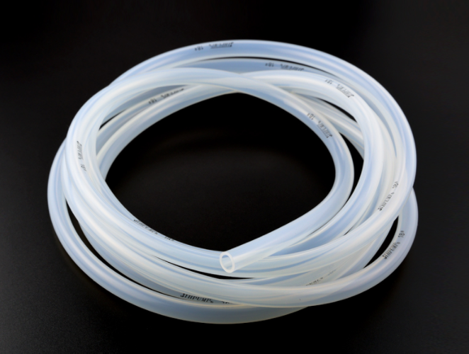
Silicone Tubing
The most widely used material due to its excellent flexibility, elasticity, high biocompatibility, and cost-competitiveness. Its high transparency allows for easy visual inspection of fluid status.
Applications: Food and beverage filling, basic laboratory fluid transfer, and pharmaceutical peripheral transport.
Limitation: It is relatively soft and prone to expansion deformation under high pressure. Avoid thin-walled silicone for high-pressure setups; choose thick-walled options instead.
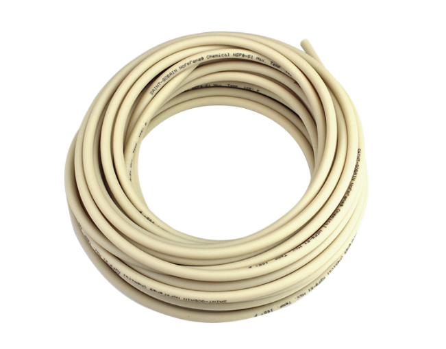
PharMed® Tubing (e.g., PharMed BPT)
Specifically engineered for rigorous industrial and pharmaceutical environments requiring continuous operation. It offers an exceptionally long mechanical life (typically over 30 times that of standard silicone), outstanding fatigue resistance, excellent gas barrier properties, and withstands repeated autoclaving.
Applications: Diagnostic kit production lines, cell culture fermenter feeding, bioreactors, and 24-hour continuous precision metering.
Limitation: Because its dimensions resist deformation under long-term occlusion, it serves as the premier choice for high-precision filling lines.
Tygon® Tubing
A large family of high-performance industrial formulations featuring broad chemical compatibility, tailored to resist specific chemicals. Its ultra-smooth inner surface prevents scaling and offers robust resistance to acids, bases, and organic solvents.
Applications: Industrial chemical dosing, wastewater sampling, handling highly corrosive laboratory chemicals.
Limitation: Always match the specific Tygon formulation code (e.g., E-3603, F-4040-A) alongside physical ID/OD sizing.
Viton® Tubing
A high-performance fluoroelastomer (FKM) material offering premium temperature tolerance and unmatched resistance to strong acids, bases, powerful oxidizers, organic solvents, fuels, and lubricants.
Applications: Petrochemical fluid control, paint and coating spraying, high-temperature media transport.
Limitation: Viton is relatively stiff and exhibits slower restitution. Ensure the drive motor delivers ample torque to prevent stalling.
How to Select the Right Peristaltic Pump Tubing Size?
1. Target the Desired Flow Rate
Determine your process requirement per unit of time (e.g., 50 mL/min, 500 mL/min, or 5 L/min). As a rule of thumb, select a tubing ID that allows the driver to run within 30% to 70% of its maximum speed. Running a drive at 100% speed continuously accelerates tubing aging, while running at extremely low speeds (e.g., < 5 RPM) sacrifices metering accuracy.
2. Verify Pump Head Compatibility
Pump heads feature fixed roller gaps and retention mechanisms. They support a strict range of tubing sizes. Check the pump head manual to confirm that the ID, OD, and wall thickness match perfectly, taking care not to confuse metric (mm) and imperial (inch) units.
3. Consider Fluid Properties
Should the fluid handled be acid, alkaline, or solvent, make sure to cross-check against a Chemical Compatibility Chart. In cases of very viscous fluids or slurries with particles in suspension, oversize the diameter of the tube by 1 or 2 sizes to minimize frictional resistance and blockage in the tubing.
4. Review Duty Cycle
In case you have a setup that is used in an industrial process for more than 12 to 24 hours each day, ensure you do not choose thin wall silicone tubing or cheap silicone tubes. Rather choose 2.4 mm or 3.2 mm thick wall silicone tubing in conjunction with PharMed BPT material.
Common Mistakes to Avoid in Peristaltic Pump Tubing Sizing
Ignoring Pump Head Limits: Buying tubing based solely on target flow rate, only to find the wall thickness is too thin for the pump head to clamp, resulting in a total loss of suction.
Focusing Only on ID: Assuming that matching IDs makes tubes interchangeable. Ignoring OD variances leads to improper occlusion (causing backflow if too small) or severe wear (causing motor overload if too large).
Neglecting Wall Thickness: Using thin-walled tubing under backpressure or high-suction conditions, causing the tube to collapse flat under system vacuum without springing back.
Substituting Standard Medical/Silicone Hoses: Using non-peristaltic rated tubing. These generic hoses exhibit poor mechanical tolerances (uneven ID/OD) and cannot withstand repeated occlusion, leading to drastic flow drift and rupture within hours.
Overlooking Chemical-Induced Swelling: Selecting an incompatible material that swells when exposed to the fluid, destroying the original mechanical fit within the pump head.
When Should You Replace Peristaltic Pump Tubing?
Tubing is a high-frequency consumable component. Ensure there is a predictive maintenance plan in place to immediately replace the peristaltic pump tubing in the event of any of the following symptoms:
Flow Reduction in Measurement: If there is a reduction in flow rate by 5-10% at the same RPM without any blockages, then the tubing is suffering from mechanical creep, leading to lack of restitution.
Grooves or Wall Thinning in Locality: Caused due to continuous friction on the tube walls from the pump rollers.
Cracking or Stress Whitening: The tubing has exceeded its fatigue point and will likely fail soon.
Color Changes, Tackiness or Lack of Elasticity: Symptoms of chemical degradation of the tubing due to the pumped fluid.
Unusual Pump Head Sounds: Possible symptom of tubing swelling or misalignment due to mechanical interference.
Conclusion
Correct selection of peristaltic pump tubing geometry and material formulation creates the basis for reliable liquid transport, accurate flow measurement, and getting full value out of your pumping equipment.
JIHPump, a specialized producer of precision fluid control systems, offers a full array of both stock and customized peristaltic pumps, including matching tubing. For challenging applications that involve liquids with high viscosity, high backpressure, corrosiveness, or critical biological/pharmaceutical contamination requirements, JIHPump can provide the precise combination of geometry and formulation.
Reach out to us today to have our application engineers fine-tune your fluid delivery system to its best performance.